本文為英文版的機器翻譯版本,如內容有任何歧義或不一致之處,概以英文版為準。
# 在 SDK 中建構電路
本節提供定義電路、檢視可用閘道、延伸電路和檢視每個裝置支援之閘道的範例。它還包含有關如何手動配置 的說明qubits、指示編譯器完全按照定義執行您的電路,以及使用雜訊模擬器建置雜訊電路。
您也可以使用 Braket 中的脈衝層級,處理具有特定 QPUs 的各種閘道。如需詳細資訊,請參閱 [Amazon Braket 上的脈衝控制](braket-pulse-control.md)。
**Topics**
+ [閘道和電路](#braket-gates)
+ [程式集](#braket-program-set)
+ [部分測量](#braket-partial-measurement)
+ [手動qubit配置](#manual-qubit-allocation)
+ [逐字編譯](#verbatim-compilation)
+ [雜訊模擬](#noise-simulation)
## 閘道和電路
Quantum 閘道和電路在 Amazon Braket Python SDK 的 [https://github.com/aws/amazon-braket-sdk-python/blob/main/src/braket/circuits/circuit.py](https://github.com/aws/amazon-braket-sdk-python/blob/main/src/braket/circuits/circuit.py)類別中定義。從 SDK,您可以透過呼叫 來執行個體化新的電路物件`Circuit()`。
**範例:定義電路**
此範例一開始會定義四個 qubits(已標記 `q0`、`q2`、 `q1`和 `q3`) 的範例電路,其中包含標準、單一 qubit Hadamard 閘道和兩個 qubit CNOT 閘道。您可以透過呼叫 `print`函數來視覺化此電路,如下列範例所示。
```
# Import the circuit module
from braket.circuits import Circuit
# Define circuit with 4 qubits
my_circuit = Circuit().h(range(4)).cnot(control=0, target=2).cnot(control=1, target=3)
print(my_circuit)
```
```
T : │ 0 │ 1 │
┌───┐
q0 : ─┤ H ├───●─────────
└───┘ │
┌───┐ │
q1 : ─┤ H ├───┼─────●───
└───┘ │ │
┌───┐ ┌─┴─┐ │
q2 : ─┤ H ├─┤ X ├───┼───
└───┘ └───┘ │
┌───┐ ┌─┴─┐
q3 : ─┤ H ├───────┤ X ├─
└───┘ └───┘
T : │ 0 │ 1 │
```
**範例:定義參數化電路**
在此範例中,我們定義一個電路,其中包含相依於可用參數的閘道。我們可以指定這些參數的值來建立新的電路,或在提交電路時,在特定裝置上做為量子任務執行。
```
from braket.circuits import Circuit, FreeParameter
# Define a FreeParameter to represent the angle of a gate
alpha = FreeParameter("alpha")
# Define a circuit with three qubits
my_circuit = Circuit().h(range(3)).cnot(control=0, target=2).rx(0, alpha).rx(1, alpha)
print(my_circuit)
```
您可以從參數化的電路建立新的非參數化電路,方法是提供單一 `float`(所有可用參數將採用的值) 或關鍵字引數,指定每個參數的值給電路,如下所示。
```
my_fixed_circuit = my_circuit(1.2)
my_fixed_circuit = my_circuit(alpha=1.2)
print(my_fixed_circuit)
```
請注意, `my_circuit` 未修改,因此您可以使用它來執行個體化許多具有固定參數值的新電路。
**範例:修改電路中的閘道**
下列範例定義具有使用控制和電源修改器之閘道的電路。您可以使用這些修改來建立新的閘道,例如受控`Ry`閘道。
```
from braket.circuits import Circuit
# Create a bell circuit with a controlled x gate
my_circuit = Circuit().h(0).x(control=0, target=1)
# Add a multi-controlled Ry gate of angle .13
my_circuit.ry(angle=.13, target=2, control=(0, 1))
# Add a 1/5 root of X gate
my_circuit.x(0, power=1/5)
print(my_circuit)
```
閘道修改器僅支援本機模擬器。
**範例:查看所有可用的閘道**
下列範例顯示如何在 Amazon Braket 中查看所有可用的閘道。
```
from braket.circuits import Gate
# Print all available gates in Amazon Braket
gate_set = [attr for attr in dir(Gate) if attr[0].isupper()]
print(gate_set)
```
此程式碼的輸出會列出所有閘道。
```
['CCNot', 'CNot', 'CPhaseShift', 'CPhaseShift00', 'CPhaseShift01', 'CPhaseShift10', 'CSwap', 'CV', 'CY', 'CZ', 'ECR', 'GPhase', 'GPi', 'GPi2', 'H', 'I', 'ISwap', 'MS', 'PRx', 'PSwap', 'PhaseShift', 'PulseGate', 'Rx', 'Ry', 'Rz', 'S', 'Si', 'Swap', 'T', 'Ti', 'U', 'Unitary', 'V', 'Vi', 'X', 'XX', 'XY', 'Y', 'YY', 'Z', 'ZZ']
```
任何這些閘道都可以透過呼叫該類型電路的 方法附加到電路。例如,呼叫 `circ.h(0)`,將 Hadamard 閘道新增至第一個 qubit。
**注意**
閘道會附加到適當位置,以下範例會將上一個範例中列出的所有閘道新增至相同的電路。
```
circ = Circuit()
# toffoli gate with q0, q1 the control qubits and q2 the target.
circ.ccnot(0, 1, 2)
# cnot gate
circ.cnot(0, 1)
# controlled-phase gate that phases the |11> state, cphaseshift(phi) = diag((1,1,1,exp(1j*phi))), where phi=0.15 in the examples below
circ.cphaseshift(0, 1, 0.15)
# controlled-phase gate that phases the |00> state, cphaseshift00(phi) = diag([exp(1j*phi),1,1,1])
circ.cphaseshift00(0, 1, 0.15)
# controlled-phase gate that phases the |01> state, cphaseshift01(phi) = diag([1,exp(1j*phi),1,1])
circ.cphaseshift01(0, 1, 0.15)
# controlled-phase gate that phases the |10> state, cphaseshift10(phi) = diag([1,1,exp(1j*phi),1])
circ.cphaseshift10(0, 1, 0.15)
# controlled swap gate
circ.cswap(0, 1, 2)
# swap gate
circ.swap(0,1)
# phaseshift(phi)= diag([1,exp(1j*phi)])
circ.phaseshift(0,0.15)
# controlled Y gate
circ.cy(0, 1)
# controlled phase gate
circ.cz(0, 1)
# Echoed cross-resonance gate applied to q0, q1
circ = Circuit().ecr(0,1)
# X rotation with angle 0.15
circ.rx(0, 0.15)
# Y rotation with angle 0.15
circ.ry(0, 0.15)
# Z rotation with angle 0.15
circ.rz(0, 0.15)
# Hadamard gates applied to q0, q1, q2
circ.h(range(3))
# identity gates applied to q0, q1, q2
circ.i([0, 1, 2])
# iswap gate, iswap = [[1,0,0,0],[0,0,1j,0],[0,1j,0,0],[0,0,0,1]]
circ.iswap(0, 1)
# pswap gate, PSWAP(phi) = [[1,0,0,0],[0,0,exp(1j*phi),0],[0,exp(1j*phi),0,0],[0,0,0,1]]
circ.pswap(0, 1, 0.15)
# X gate applied to q1, q2
circ.x([1, 2])
# Y gate applied to q1, q2
circ.y([1, 2])
# Z gate applied to q1, q2
circ.z([1, 2])
# S gate applied to q0, q1, q2
circ.s([0, 1, 2])
# conjugate transpose of S gate applied to q0, q1
circ.si([0, 1])
# T gate applied to q0, q1
circ.t([0, 1])
# conjugate transpose of T gate applied to q0, q1
circ.ti([0, 1])
# square root of not gate applied to q0, q1, q2
circ.v([0, 1, 2])
# conjugate transpose of square root of not gate applied to q0, q1, q2
circ.vi([0, 1, 2])
# exp(-iXX theta/2)
circ.xx(0, 1, 0.15)
# exp(i(XX+YY) theta/4), where theta=0.15 in the examples below
circ.xy(0, 1, 0.15)
# exp(-iYY theta/2)
circ.yy(0, 1, 0.15)
# exp(-iZZ theta/2)
circ.zz(0, 1, 0.15)
# IonQ native gate GPi with angle 0.15 applied to q0
circ.gpi(0, 0.15)
# IonQ native gate GPi2 with angle 0.15 applied to q0
circ.gpi2(0, 0.15)
# IonQ native gate MS with angles 0.15, 0.15, 0.15 applied to q0, q1
circ.ms(0, 1, 0.15, 0.15, 0.15)
```
除了預先定義的閘道集之外,您也可以將自行定義的單一閘道套用至電路。這些可以是單一 qubit 閘道 (如下列原始碼所示) 或套用到 `targets` 參數qubits所定義 的多 qubit 閘道。
```
import numpy as np
# Apply a general unitary
my_unitary = np.array([[0, 1],[1, 0]])
circ.unitary(matrix=my_unitary, targets=[0])
```
**範例:擴展現有電路**
您可以新增指示來擴展現有的電路。`Instruction` 是量子指令,描述在量子裝置上執行的量子任務。 `Instruction`運算子`Gate`僅包含 類型的物件。
```
# Import the Gate and Instruction modules
from braket.circuits import Gate, Instruction
# Add instructions directly.
circ = Circuit([Instruction(Gate.H(), 4), Instruction(Gate.CNot(), [4, 5])])
# Or with add_instruction/add functions
instr = Instruction(Gate.CNot(), [0, 1])
circ.add_instruction(instr)
circ.add(instr)
# Specify where the circuit is appended
circ.add_instruction(instr, target=[3, 4])
circ.add_instruction(instr, target_mapping={0: 3, 1: 4})
# Print the instructions
print(circ.instructions)
# If there are multiple instructions, you can print them in a for loop
for instr in circ.instructions:
print(instr)
# Instructions can be copied
new_instr = instr.copy()
# Appoint the instruction to target
new_instr = instr.copy(target=[5, 6])
new_instr = instr.copy(target_mapping={0: 5, 1: 6})
```
**範例:檢視每個裝置支援的閘道**
模擬器支援 Braket SDK 中的所有閘道,但 QPU 裝置支援較小的子集。您可以在裝置屬性中找到裝置支援的閘道。以下顯示 IonQ 裝置的範例:
```
# Import the device module
from braket.aws import AwsDevice
device = AwsDevice("arn:aws:braket:us-east-1::device/qpu/ionq/Aria-1")
# Get device name
device_name = device.name
# Show supportedQuantumOperations (supported gates for a device)
device_operations = device.properties.dict()['action']['braket.ir.openqasm.program']['supportedOperations']
print('Quantum Gates supported by {}:\n {}'.format(device_name, device_operations))
```
```
Quantum Gates supported by Aria 1:
['x', 'y', 'z', 'h', 's', 'si', 't', 'ti', 'v', 'vi', 'rx', 'ry', 'rz', 'cnot', 'swap', 'xx', 'yy', 'zz']
```
支援的閘道可能需要編譯為原生閘道,才能在量子硬體上執行。當您提交電路時, Amazon Braket 會自動執行此編譯。
**範例:以程式設計方式擷取裝置支援的原生閘道的逼真度**
您可以在 Braket 主控台**的裝置**頁面上檢視逼真度資訊。有時,以程式設計方式存取相同的資訊會很有幫助。下列程式碼示範如何在 QPU 的兩個qubit閘道之間擷取兩個閘道逼真度。
```
# Import the device module
from braket.aws import AwsDevice
device = AwsDevice("arn:aws:braket:us-west-1::device/qpu/rigetti/Ankaa-3")
# Specify the qubits
a=10
b=11
edge_properties_entry = device.properties.standardized.twoQubitProperties['10-11'].twoQubitGateFidelity
gate_name = edge_properties_entry[0].gateName
fidelity = edge_properties_entry[0].fidelity
print(f"Fidelity of the {gate_name} gate between qubits {a} and {b}: {fidelity}")
```
## 程式集
程式集可在單一量子任務中有效率地執行多個量子電路。在該任務中,您最多可以提交 100 個量子電路,或具有最多 100 個不同參數集的單一參數電路。此操作可將後續電路執行之間的時間降至最低,並減少量子任務處理額外負荷。目前,Amazon Braket Local Simulator和 AQT、 IQM和 Rigetti 裝置支援程式集。
**定義 ProgramSet**
下列第一個程式碼範例示範如何使用參數化電路和不含參數的電路`ProgramSet`來建置 。
```
from braket.aws import AwsDevice
from braket.circuits import Circuit, FreeParameter
from braket.program_sets.circuit_binding import CircuitBinding
from braket.program_sets import ProgramSet
# Initialize the quantum device
device = AwsDevice("arn:aws:braket:eu-north-1::device/qpu/iqm/Garnet")
# Define circuits
circ1 = Circuit().h(0).cnot(0, 1)
circ2 = Circuit().rx(0, 0.785).ry(1, 0.393).cnot(1, 0)
circ3 = Circuit().t(0).t(1).cz(0, 1).s(0).cz(1, 2).s(1).s(2)
parameterize_circuit = Circuit().rx(0, FreeParameter("alpha")).cnot(0, 1).ry(1, FreeParameter("beta"))
# Create circuit bindings with different parameters
circuit_binding = CircuitBinding(
circuit=parameterize_circuit,
input_sets={
'alpha': (0.10, 0.11, 0.22, 0.34, 0.45),
'beta': (1.01, 1.01, 1.03, 1.04, 1.04),
})
# Creating the program set
program_set_1 = ProgramSet([
circ1,
circ2,
circ3,
circuit_binding,
])
```
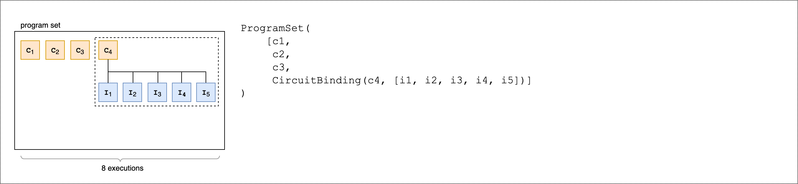
此程式集包含四個唯一的程式:`circ1`、`circ3`、 `circ2`和 `circuit_binding`。`circuit_binding` 程式使用五個不同的參數繫結執行,建立五個可執行檔。其他三個無參數程式則各自建立一個可執行檔。這會產生總共八個可執行檔,如下圖所示。
下列第二個程式碼範例示範如何使用 `product()`方法,將同一組可觀測值連接到程式集的每個可執行檔。
```
from braket.circuits.observables import I, X, Y, Z
observables = [Z(0) @ Z(1), X(0) @ X(1), Z(0) @ X(1), X(0) @ Z(1)]
program_set_2 = ProgramSet.product(
circuits=[circ1, circ2, circuit_binding],
observables=observables
)
```
對於無參數程式,會針對每個電路測量每個可觀測項目。對於參數程式,會為每個輸入集測量每個可觀測值,如下圖所示。

下列第三個程式碼範例示範如何使用 `zip()`方法,將個別可觀測項目與 中的特定參數集配對`ProgramSet`。
```
program_set_3 = ProgramSet.zip(
circuits=circuit_binding,
observables=observables + [Y(0) @ Y(1)]
)
```
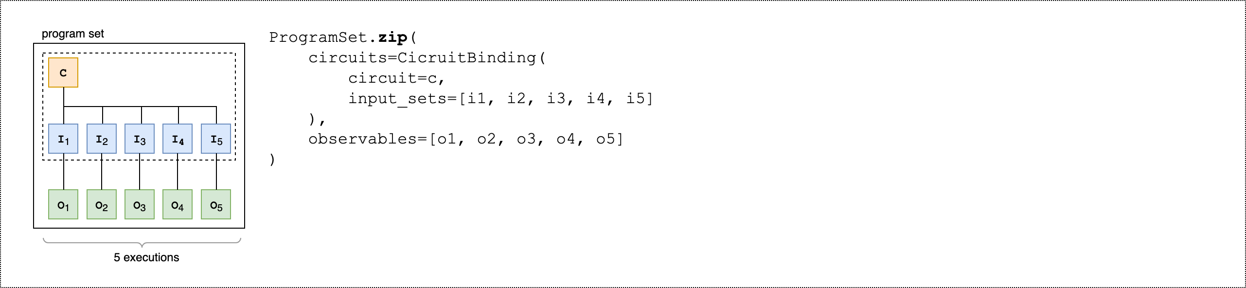
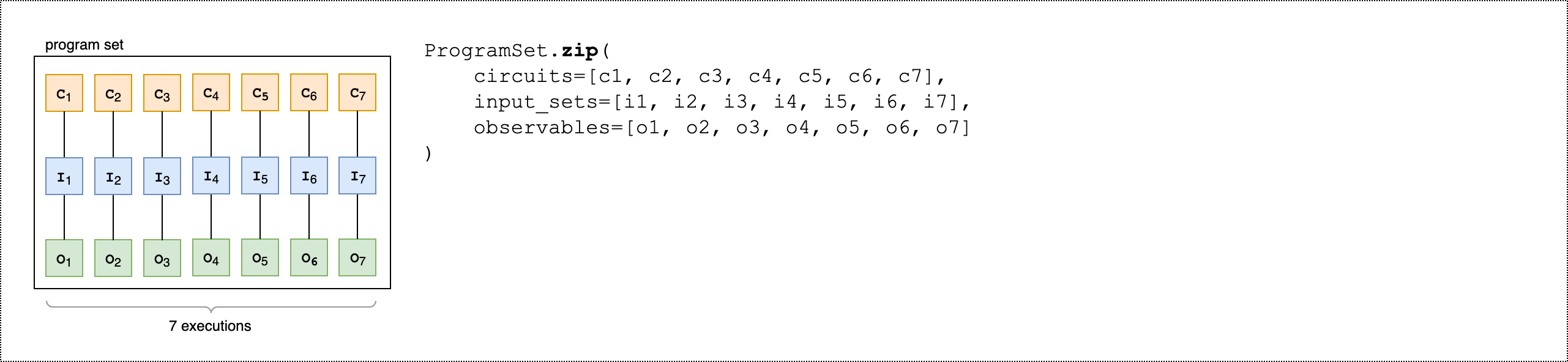
您可以直接壓縮具有電路和輸入集清單的可觀測項目清單`CircuitBinding()`,而不是 。
```
program_set_4 = ProgramSet.zip(
circuits=[circ1, circ2, circ3],
input_sets=[{}, {}, {}],
observables=observables[:3]
)
```
如需程式集的詳細資訊和範例,請參閱 amazon-braket-examples Github 中的[程式集資料夾](https://github.com/amazon-braket/amazon-braket-examples/tree/main/examples/braket_features/program_sets)。
**檢查並在裝置上執行程式集**
程式集的可執行計數等於其唯一參數繫結電路的數量。使用以下程式碼範例計算電路可執行檔和鏡頭的總數。
```
# Number of shots per executable
shots = 10
num_executables = program_set_1.total_executables
# Calculate total number of shots across all executables
total_num_shots = shots*num_executables
```
**注意**
使用程式集,您可以根據程式集中所有電路的拍攝總數,支付單一任務費用和每個拍攝費用。
若要執行程式集,請使用下列程式碼範例。
```
# Run the program set
task = device.run(
program_set_1, shots=total_num_shots,
)
```
使用Rigetti裝置時,您的程式集可能會在任務部分完成且部分排入佇列時保持在 `RUNNING` 狀態。如需更快的結果,請考慮將您的程式集提交為[混合任務](braket-jobs-first.md)。
**分析結果**
執行下列程式碼來分析和測量 中可執行檔的結果`ProgramSet`。
```
# Get the results from a program set
result = task.result()
# Get the first executbable
first_program = result[0]
first_executable = first_program[0]
# Inspect the results of the first executable
measurements_from_first_executable = first_executable.measurements
print(measurements_from_first_executable)
```
## 部分測量
使用部分測量來測量個別的 qubit 或一部分的 qubit,而不是測量量子電路中的所有 qubit。
**注意**
中電路測量和前饋操作等其他功能可作為實驗功能使用,請參閱[存取 IQM 裝置上的動態電路](braket-experimental-capabilities.md#braket-access-dynamic-circuits)。
**範例:測量 qubit 的子集**
下列程式碼範例透過在 Bell 狀態電路中僅測量 qubit 0 來示範部分測量。
```
from braket.devices import LocalSimulator
from braket.circuits import Circuit
# Use the local state vector simulator
device = LocalSimulator()
# Define an example bell circuit and measure qubit 0
circuit = Circuit().h(0).cnot(0, 1).measure(0)
# Run the circuit
task = device.run(circuit, shots=10)
# Get the results
result = task.result()
# Print the circuit and measured qubits
print(circuit)
print()
print("Measured qubits: ", result.measured_qubits)
```
## 手動qubit配置
當您從 在量子電腦上執行量子電路時Rigetti,您可以選擇使用手動qubit配置來控制qubits用於演算法的 。[Amazon Braket 主控台](https://console.aws.amazon.com/braket/home)和 [Amazon Braket SDK](https://github.com/aws/amazon-braket-sdk-python) 可協助您檢查所選量子處理單元 (QPU) 裝置的最新校正資料,以便qubits為實驗選擇最佳校正資料。
手動qubit配置可讓您以更高的準確性執行電路,並調查個別qubit屬性。研究人員和進階使用者會根據最新的裝置校正資料來最佳化其電路設計,並可取得更準確的結果。
下列範例示範如何qubits明確配置 。
```
# Import the device module
from braket.aws import AwsDevice
device = AwsDevice("arn:aws:braket:us-west-1::device/qpu/rigetti/Ankaa-3")
circ = Circuit().h(0).cnot(0, 7) # Indices of actual qubits in the QPU
# Set up S3 bucket (where results are stored)
my_bucket = "amazon-braket-s3-demo-bucket" # The name of the bucket
my_prefix = "your-folder-name" # The name of the folder in the bucket
s3_location = (my_bucket, my_prefix)
my_task = device.run(circ, s3_location, shots=100, disable_qubit_rewiring=True)
```
如需詳細資訊,請參閱 [ GitHub 上的 Amazon Braket 範例](https://github.com/aws/amazon-braket-examples),或更具體而言,此筆記本:在 [QPU 裝置上配置 Qubit](https://github.com/aws/amazon-braket-examples/blob/main/examples/braket_features/Allocating_Qubits_on_QPU_Devices.ipynb)。
## 逐字編譯
當您在以閘道為基礎的量子電腦上執行量子電路時,您可以指示編譯器完全按照定義執行電路,而無需進行任何修改。使用逐字編譯,您可以指定精確地保留整個電路,或僅保留其特定部分 (Rigetti僅 支援)。開發硬體基準測試或錯誤緩解通訊協定的演算法時,您可以選擇精確指定硬體上執行的閘道和電路配置。逐字編譯可讓您關閉特定最佳化步驟,直接控制編譯程序,從而確保電路完全按照設計執行。
AQT、、 和 Rigetti 裝置支援逐字編譯IonQIQM,且需要使用原生閘道。使用逐字編譯時,建議您檢查裝置的拓撲,以確保在連接的 上呼叫閘道,qubits以及電路使用硬體上支援的原生閘道。下列範例示範如何以程式設計方式存取裝置支援的原生閘道清單。
```
device.properties.paradigm.nativeGateSet
```
對於 Rigetti,必須透過設定 `disableQubitRewiring=True`與逐字編譯搭配使用來關閉qubit重新配線。如果在編譯中使用逐字方塊時設定 `disableQubitRewiring=False` ,則量子電路會驗證失敗且不會執行。
如果為電路啟用逐字編譯,並在不支援它的 QPU 上執行,則會產生錯誤,指出不支援的操作導致任務失敗。隨著更多量子硬體原生支援編譯器函數,此功能將擴展為包含這些裝置。使用下列程式碼查詢時,支援逐字編譯的裝置會將其納入支援的操作。
```
from braket.aws import AwsDevice
from braket.device_schema.device_action_properties import DeviceActionType
device = AwsDevice("arn:aws:braket:us-west-1::device/qpu/rigetti/Ankaa-3")
device.properties.action[DeviceActionType.OPENQASM].supportedPragmas
```
使用逐字編譯不會產生額外的成本。根據您在 [Amazon Braket 定價](https://aws.amazon.com/braket/pricing/)頁面上指定的目前費率,在 Braket QPU 裝置、筆記本執行個體和隨需模擬器上執行的量子任務,會繼續向您收取費用。如需詳細資訊,請參閱 [Verbatim 編譯](https://github.com/aws/amazon-braket-examples/blob/main/examples/braket_features/Verbatim_Compilation.ipynb)範例筆記本。
**注意**
如果您使用 OpenQASM 為 AQT和 IonQ 裝置寫入電路,而且您希望將電路直接映射至實體 qubit,則需要使用 ,`#pragma braket verbatim`因為 OpenQASM 忽略`disableQubitRewiring`標記。
## 雜訊模擬
若要執行個體化本機雜訊模擬器,您可以變更後端,如下所示。
```
# Import the device module
from braket.aws import AwsDevice
device = LocalSimulator(backend="braket_dm")
```
您可以透過兩種方式建置雜訊電路:
1. 從下而上建置雜訊電路。
1. 採用現有的無雜訊電路,並注入雜訊。
下列範例顯示使用具有去極化雜訊的基本電路和自訂 Kraus 頻道的方法。
```
import scipy.stats
import numpy as np
# Bottom up approach
# Apply depolarizing noise to qubit 0 with probability of 0.1
circ = Circuit().x(0).x(1).depolarizing(0, probability=0.1)
# Create an arbitrary 2-qubit Kraus channel
E0 = scipy.stats.unitary_group.rvs(4) * np.sqrt(0.8)
E1 = scipy.stats.unitary_group.rvs(4) * np.sqrt(0.2)
K = [E0, E1]
# Apply a two-qubit Kraus channel to qubits 0 and 2
circ = circ.kraus([0, 2], K)
```
```
from braket.circuits import Noise
# Inject noise approach
# Define phase damping noise
noise = Noise.PhaseDamping(gamma=0.1)
# The noise channel is applied to all the X gates in the circuit
circ = Circuit().x(0).y(1).cnot(0, 2).x(1).z(2)
circ_noise = circ.copy()
circ_noise.apply_gate_noise(noise, target_gates=Gate.X)
```
執行電路的使用者體驗與之前相同,如下列兩個範例所示。
**範例 1**
```
task = device.run(circ, shots=100)
```
或
**範例 2**
```
task = device.run(circ_noise, shots=100)
```
如需更多範例,請參閱 [Braket 雜訊模擬器簡介範例](https://github.com/aws/amazon-braket-examples/blob/main/examples/braket_features/Simulating_Noise_On_Amazon_Braket.ipynb)