Elastic Disaster Recovery network diagrams
AWS Elastic Disaster Recovery supports the following source infrastructure types:
On-premises to AWS – Protect physical or virtual servers in your data center by replicating to an AWS Region.
AWS to AWS (cross-Region) – Protect Amazon EC2 instances by replicating from one AWS Region to another. Cross-Region replication is recommended for disaster recovery to help protect against Region-level events.
AWS to AWS (cross-Availability Zone) – Replicate Amazon EC2 instances to a different Availability Zone within the same AWS Region. For comprehensive disaster recovery protection, we recommend cross-Region replication.
VMware to AWS – Protect VMware vSphere environments, including both on-premises vSphere and VMware Cloud on AWS. See Disaster recovery for VMware Cloud on AWS using AWS Elastic Disaster Recovery
. Other clouds to AWS – Protect workloads running on other cloud providers such as Microsoft Azure or Google Cloud. See Building a disaster recovery site on AWS for workloads on Microsoft Azure
. AWS to on-premises (failback) – After a disaster recovery event, fail back from AWS to your original source environment.
The following are the network diagrams for AWS Elastic Disaster Recovery :
General Architecture - On-Premises to AWS
This diagram shows the general architecture of DRS protecting source servers located in an on-premises environment.

On-Prem to AWS
This diagram shows the network architecture of DRS protecting source servers located in an on-premises environment.

AWS Cloud to AWS Cloud via VPC Peering
This diagram shows the network architecture of AWS DRS protecting source servers located in an AWS VPC. Data replication between the source VPC and the target staging area, along with communication with the AWS DRS service, flows through a VPC peering connection.

On-Prem to Outposts
This diagram shows the network architecture of DRS protecting source servers located in an on-premises environment. The staging and recovery are both located on AWS Outposts. Find out more about protecting source servers using Outposts.

AWS to Outposts
This diagram shows the network architecture of DRS protecting source servers located in AWS. The staging and recovery are both located on AWS Outposts. Find out more about protecting source servers using Outposts.

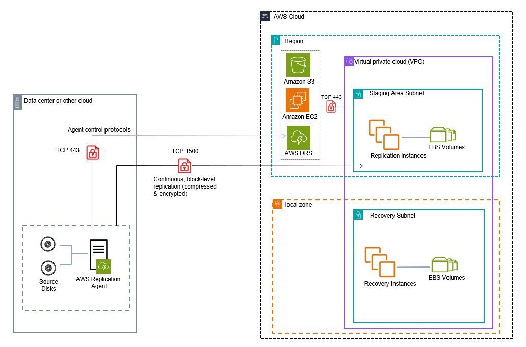
On-Premises to AWS Local Zone
This diagram shows the network architecture of DRS protecting source servers located in an on-premises environment. The staging area is located in an AWS Region and the recovery is in an AWS Local Zone.
AWS Local Zone to Region
This diagram shows the network architecture of DRS protecting source servers located in an AWS Local Zone. The staging and recovery environment are both located in an AWS Region.

AWS Local Zone to AWS Local Zone
This diagram shows the network architecture of DRS protecting source servers located in an AWS Local Zone. The staging environment is located in an AWS Region and the recovery environment is in another AWS Local Zone.

AWS Failback to On-Prem
This diagram shows the network architecture of DRS performing Failback to an on-premises environment after performing a recovery into AWS.

