Amazon EC2 拓扑工作原理
AWS 网络采用分层式层次结构。EC2 实例在第三层或更低层连接到网络,具体取决于实例类型。实例的拓扑结构可描述为一组节点,网络中的每层一个节点。借助 DescribeInstanceTopology 或 DescribeCapacityReservationTopology API 响应中返回的节点集,可以自上而下地总览网络层次结构,底层节点会连接到实例。
注意
有些实例类型的节点组合包含 4 个网络节点,代表网络中共有 4 层;另一些实例类型的节点组合包含 3 个网络节点,代表网络中共有 3 层。有关受支持的实例类型,请参阅实例类型。
您可能只会看到 1、2 或 3 个网络节点,具体取决于容量预留的类型。
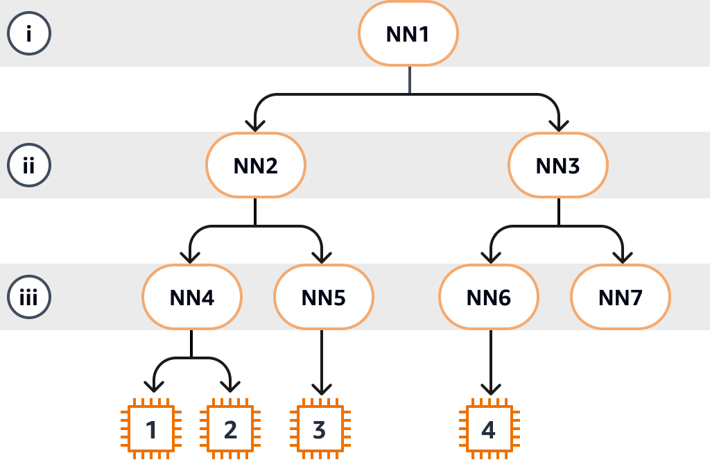
下图提供了可视化表示,您可以使用其来理解 EC2 拓扑。网络节点被标识为 NN1 – NN7。数字符号 i、ii 和 iii 用于标识网络层。数字 1、2、3 和 4 用于标识 EC2 实例。实例连接到位于底层(下图中用 iii 标识)的节点。多个实例可以连接到同一个节点。
在本示例中:
-
实例 1 连接到第 iii 层中的网络节点 4(NN4)。NN4 连接到第 ii 层的网络节点 2(NN2),NN2 连接到第 i 层中的网络节点 1(NN1),第 i 层是本示例中网络层次结构的顶层。网络节点集包括 NN1、NN2 和 NN4,按从上层到底层的顺序分层表示。
-
实例 2 还连接到网络节点 4(NN4)。实例 1 和实例 2 共享相同的网络节点集:NN1、NN2 和 NN4。
-
实例 3 连接到网络节点 5(NN5)。NN5 连接到 NN2,而 NN2 连接到 NN1。实例 3 网络节点集是 NN1、NN2 和 NN5。
-
实例 4 连接到网络节点 6(NN6)。其网络节点集是 NN1、NN3 和 NN6。
考虑实例 1、实例 2 和实例 3 的邻近性时,实例 1 和实例 2 彼此靠得更近,因为其连接到同一个网络节点(NN4),而实例 3 则较远,因为其连接到不同的网络节点(NN5)。
在考虑此图中所有实例的邻近性时,实例 1、实例 2 和实例 3 彼此之间比其与实例 4 之间的距离更近,因为这几个实例在网络节点集中共享 NN2。
一般来说,如果连接到任意两个实例的网络节点相同,则这些实例在物理上彼此靠近,就像实例 1 和实例 2 一样。此外,网络节点之间的跳数越少,实例之间的距离就越近。例如,实例 1 和实例 3 到共同网络节点(NN2)的跳数少于其与实例 4 共同网络节点(NN1)的跳数,因此实例 1 和实例 3 彼此之间的距离比到实例 4 更近。
在此示例中,没有实例在网络节点 7(NN7)下运行,因此 API 输出将不包括 NN7。
如何解释 DescribeInstanceTopology 输出
您可以使用 DescribeInstanceTopology API 来描述实例拓扑。输出提供了实例底层网络拓扑的分层视图。
以下示例输出对应于上图中四个实例的网络拓扑信息。出于本示例的演示目的,示例中包含注释。
输出中的以下信息需要注意:
-
NetworkNodes描述了单个实例的网络节点集。 -
在每个网络节点集中,网络节点按从上到下的分层顺序列出。
-
连接到实例的网络节点是列表中最后的网络节点(底层)。
-
要确定哪些实例彼此靠近,请先在底层找到共同的网络节点。如果底层没有共同的网络节点,则在上层中查找共同的网络节点。
在以下示例输出中,i-1111111111example 和 i-2222222222example 与本示例中的其他实例相比彼此最靠近,因为其在底层具有共同的网络节点 nn-4444444444example。
注意
响应中包含 3 个或以上网络节点。要了解每种受支持实例类型的响应中的网络节点数量,请参阅实例类型。
{
    "Instances": [
        {
            "InstanceId": "i-1111111111example",  //Corresponds to instance 1
            "InstanceType": "p4d.24xlarge",
            "GroupName": "ML-group",
            "NetworkNodes": [
                "nn-1111111111example",           //Corresponds to NN1 in layer i
                "nn-2222222222example",           //Corresponds to NN2 in layer ii
                "nn-4444444444example"            //Corresponds to NN4 in layer iii - bottom layer, connected to the instance
            ],
            "CapacityBlockId": "null",
            "ZoneId": "usw2-az2",
            "AvailabilityZone": "us-west-2a"
        },
        {
            "InstanceId": "i-2222222222example",  //Corresponds to instance 2
            "InstanceType": "p4d.24xlarge",
            "NetworkNodes": [
                "nn-1111111111example",           //Corresponds to NN1 - layer i
                "nn-2222222222example",           //Corresponds to NN2 - layer ii
                "nn-4444444444example"            //Corresponds to NN4 - layer iii - connected to instance
            ],
            "CapacityBlockId": "null",
            "ZoneId": "usw2-az2",
            "AvailabilityZone": "us-west-2a"
        },
        {
            "InstanceId": "i-3333333333example",  //Corresponds to instance 3
            "InstanceType": "trn1.32xlarge",
            "NetworkNodes": [
                "nn-1111111111example",           //Corresponds to NN1 - layer i
                "nn-2222222222example",           //Corresponds to NN2 - layer ii
                "nn-5555555555example"            //Corresponds to NN5 - layer iii - connected to instance
            ],
            "CapacityBlockId": "null",
            "ZoneId": "usw2-az2",
            "AvailabilityZone": "us-west-2a"
        },
        {
            "InstanceId": "i-444444444example",  //Corresponds to instance 4
            "InstanceType": "trn1.2xlarge",
            "NetworkNodes": [
                "nn-1111111111example",          //Corresponds to NN1 - layer i
                "nn-3333333333example",          //Corresponds to NN3 - layer ii
                "nn-6666666666example"           //Corresponds to NN6 - layer iii - connected to instance
            ],
            "CapacityBlockId": "null",
            "ZoneId": "usw2-az2",
            "AvailabilityZone": "us-west-2a"
        }
    ],
    "NextToken": "SomeEncryptedToken"
}
如何解释 DescribeCapacityReservationTopology 输出
您可以使用 DescribeCapacityReservationTopology API 来描述容量预留拓扑。输出提供了预留容量底层网络拓扑的分层视图。
以下示例输出对应于上图中的网络拓扑信息。出于本示例的演示目的,示例中包含注释。
输出中的以下信息需要注意:
-
NetworkNodes描述了单个容量预留的网络节点集。 -
在每个网络节点集中,网络节点按从上到下的分层顺序列出。
-
连接到容量预留的网络节点是列表中最后的网络节点(底层)。
-
要确定容量预留是否彼此靠近,请先在输出的底层中找到共同的网络节点。如果底层没有共同的网络节点,则在上层中查找共同的网络节点。
在以下示例输出中,cr-1111111111example 位于 nn-2222222222example 上,而 cr-2222222222example 位于 nn-3333333333example 上。由于容量预留位于 layer ii 中的不同网络节点上,因此从一个容量预留中的实例到其他容量预留中的实例的通信效率会很低。
注意
响应包含 1、2 或 3 个网络节点,具体取决于容量预留的类型。
{
    "CapacityReservations": [
        {
            "CapacityReservationId": "cr-1111111111example",
            "CapacityBlockId": "null",
            "State": "active",
            "InstanceType": "p4d.24xlarge",
            "NetworkNodes": [
                "nn-1111111111example",      //Corresponds to NN1 - layer i
                "nn-2222222222example"       //Corresponds to NN2 - layer ii
                // Visibility of additional nodes requires an instance launch and
                // the DescribeInstanceTopology API
            ],
            "AvailabilityZone": "us-west-2a"
        },
        {
            "CapacityReservationId": "cr-2222222222example",
            "CapacityBlockId": "null",
            "State": "active",
            "InstanceType": "trn1.2xlarge",
            "NetworkNodes": [
                "nn-1111111111example",      //Corresponds to NN1 - layer i
                "nn-3333333333example"       //Corresponds to NN3 - layer ii
                // Visibility of additional nodes requires an instance launch and
                // the DescribeInstanceTopology API
            ],
            "AvailabilityZone": "us-west-2a"
        }
    ],
    "NextToken": "SomeEncryptedToken"
}
DescribeInstanceTopology 与 DescribeCapacityReservationTopology 之间的区别
下表比较 DescribeInstanceTopology 与 DescribeCapacityReservationTopology API 之间的主要区别:
| 比较点 | DescribeInstanceTopology | DescribeCapacityReservationTopology |
|---|---|---|
| 使用阶段 | 启动后(执行模式) | 预启动(规划和管理模式) |
| 主要目的 | 优化正在运行的实例上的工作负载 |
实例启动之前的容量规划和容量预留管理(合并、拆分、分配) |
| 网络节点数量 |
显示正在运行的实例的所有节点。如果实例位于容量预留中,则第一个节点将匹配相应的容量预留拓扑,然后是连接到该实例的其他节点。 |
显示部分节点集,而这些节点会因容量预留状态( |
| 州 |
实例必须处于 |
容量预留必须处于 |
| 使用案例 |
|
|
* 对于适用于 Ultraservers 的容量块,描述 active 容量预留或其正在运行的实例的拓扑时,网络节点集是相同的。
